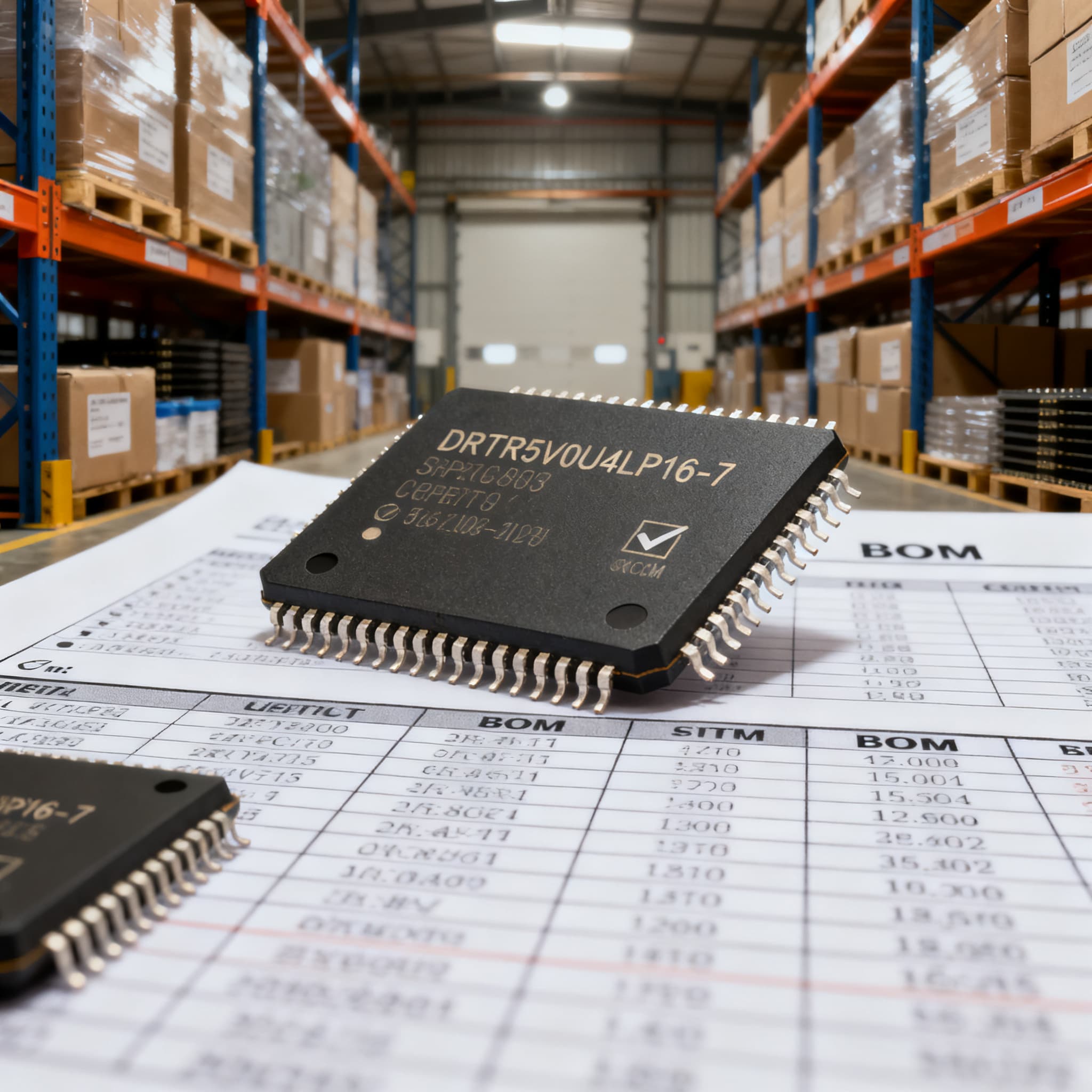
DRTR5V0U4LP16-7 Procurement Guide: Pinout and Spec Checks for RFQ
DRTR5V0U4LP16-7 procurement checklist: datasheet specs and pinout fields to verify on RFQ, plus BOM upload path on BOMNow.
Why the DRTR5V0U4LP16-7’s U-DFN1616-6 Package Trips Up RFQs (and Why It’s Worth Getting Right)
Procurement teams managing multi-line BOMs know the dread of a last-time-buy scramble triggered by a suddenly-updated lifecycle flag. A part that was “Active” yesterday can show a yellow “Not Recommended for New Designs” banner tomorrow, and if that component sits on ten different assemblies, the cost and delay ripple across an entire production schedule. TDK’s lifecycle status logic for multilayer ceramic capacitors illustrates exactly this mechanism—status transitions can happen quickly, and catching them late often means paying a premium or redesigning under pressure. The TT Electronics TN007 application note echoes that advice: instant access to lifecycle data, PCN history, and YTEOL estimates is essential before an RFQ ever leaves your desk.
The DRTR5V0U4LP16-7 from Diodes Incorporated is a perfect case. It’s a four-channel transient-voltage-suppression diode array housed in a tiny 1.6×1.6 mm U-DFN1616-6 flat no-lead package. At first glance, the 5 V standoff voltage and 0.8 pF typical capacitance suggest a straightforward USB or HDMI protection device. In practice, the combination of a leadless micro‑package, a reel‑specific “‑7” suffix, and a family that includes SOT‑23‑6 variants creates a minefield of ordering errors—wrong footprint, wrong orientation, or an unapproved substitute that slips through because the RFQ only listed “DRTR5V0U4” without the exact package and suffix. When that substitute fails at the first ESD strike because it lacked the low capacitance needed for a USB 2.0 high-speed differential pair, the root cause traces back to a poorly verified RFQ.
The value of getting the DRTR5V0U4LP16-7 specification right isn’t just about avoiding a line-down event; it’s about preserving the signal integrity that the design engineer counted on, and about having a clean, auditable paper trail when a production lot needs to be traced back to a distributor. That traceability starts with the RFQ. The following sections break down exactly what pinout traps, electrical ratings, and lifecycle checks you should verify before sending out a quote request.
Inside the DRTR5V0U4LP16-7: Pinout, Electrical Ratings, and What Matters for the RFQ
Diodes publishes the device’s specifications in datasheet DS37969 Rev. 1‑2 (also available via the Diodes download page). The DRTR5V0U4LP16-7 contains four independent, bidirectional ESD protection channels, each referenced to a common GND pad. The pinout table below maps the six‑pad U‑DFN1616‑6, which can be a source of confusion when a layout engineer inadvertently swaps I/O and GND assignments because the package is rotationally symmetric.
| Parameter | Value/Range | Unit/Notes |
|---|---|---|
| Package | U-DFN1616-6 (1.6 × 1.6 × 0.55 mm) | 6‑lead flat no‑lead; 0.5 mm pitch |
| Channels | 4 bidirectional | I/O1–I/O4, common GND on pads 2,5 |
| Reverse standoff voltage (VRWM) | 5 V max | Each channel to GND |
| Breakdown voltage (VBR) | 6.0 V min | At 1 mA |
| Clamping voltage (VC) | 12 V typ at 1 A (8/20 µs) | 15 V max under same surge |
| Junction capacitance (Cj) | 0.8 pF typ (1.5 pF max) | VR = 2.5 V, f = 1 MHz |
| ESD withstand | ±15 kV (air discharge), ±8 kV (contact) | IEC 61000‑4‑2 Level 4 |
| Peak pulse power | 60 W per channel (8/20 µs) | Derates above 25 °C |
| Operating temperature range | ‑40 to +125 °C | Junction |
| Ordering suffix | ‑7 (3,000‑piece reel) | Do not omit; see Mouser reel note |
The 0.8 pF capacitance is the headline figure that makes the DRTR5V0U4LP16-7 suitable for high‑speed interfaces like USB 3.2 Gen 1 and HDMI 2.0. When an RFQ doesn’t explicitly call for that low‑capacitance profile, a buyer might inadvertently approve a general‑purpose TVS array with 3‑5 pF—enough to distort the eye diagram and cause compliance failures. Similarly, the clamping voltage of 12 V at a 1 A surge must be checked against the absolute maximum ratings of the downstream PHY or ASIC. Most 5 V‑tolerant transceivers can handle 12 V for 20 µs, but 3.3 V I/O cells with tighter tolerances may need a lower clamp. Listing these two parameters—capacitance and clamping voltage at the specified surge current—as RFQ verification fields eliminates ambiguity.
Another subtle point is that the U‑DFN1616‑6 package has an exposed pad (GND) that must be soldered to a solid ground pour for thermal and ESD performance. Procurement doesn’t need to design the PCB, but an RFQ that includes a note like “U‑DFN1616‑6, 6‑lead, exposed pad” immediately tells the supplier which exact part to ship and helps cross‑check against the inventory label.
DRTR5V0U4LP16-7 vs. DRTR5V0U4SL-7 vs. DRTR5V0U1LP-7B: Which TVS Array Survives Your Interface?
The Diodes ESD‑protection portfolio includes several parts that superficially resemble the DRTR5V0U4LP16-7 but differ in package, channel count, and capacitance. The Lisleapex comparison of the three main contenders—DRTR5V0U4LP16-7, DRTR5V0U4SL-7, and DRTR5V0U1LP-7B—shows that assuming a drop‑in substitution is dangerous. The table below distills the differences that matter most to a procurement engineer who must decide whether to approve an alternate when the primary part is on allocation.
| Metric | DRTR5V0U4LP16-7 (Target) | DRTR5V0U4SL-7 | DRTR5V0U1LP-7B | Selection Criteria & Failure Boundary |
|---|---|---|---|---|
| Package | U‑DFN1616-6 (1.6×1.6 mm) | SOT‑23-6 (2.9×1.6 mm) | U‑DFN1006-2 (1.0×0.6 mm) | Footprint not interchangeable; SOT‑23-6 is larger and requires more board space. DFN1006‑2 is single‑channel. |
| Channel count | 4 bidirectional | 4 bidirectional | 1 bidirectional | SL‑7 matches channel count but different pin ordering (verify with muziot pin‑compatibility checklist). 1LP‑7B cannot protect a four‑line bus. |
| Junction capacitance (typ) | 0.8 pF | 1.5 pF | 0.8 pF | For USB 3.2 Gen 2 or HDMI 2.1, 1.5 pF may degrade eye opening; LP16‑7 remains the safer choice. |
| Clamping voltage (typ, 8/20 µs) | 12 V at 1 A | 13 V at 1 A | 10 V at 1 A | Lower clamping is better, but 1LP‑7B is single channel; SL‑7’s higher clamp narrows margin on sensitive ASICs. |
| Standoff voltage | 5 V | 5 V | 5 V | All suitable for 5 V tolerant I/O; 3.3 V operation is safe. |
The Makat alternatives guide stresses that a manufacturer‑designated replacement is low‑risk only when the obsolescence notice explicitly names the successor and the errata are reviewed. Diodes has not designated any of these three parts as mutual successors; they occupy different positions in the BOM. If an RFQ for the DRTR5V0U4LP16-7 yields a quote for the SL‑7 variant, the procurement team must loop in engineering to confirm pad‑for‑pad compatibility and re‑simulate signal integrity. The muziot pin‑compatibility checklist provides a practical worksheet: if any cell is unclear, treat the substitute as unverified until the manufacturer or a thorough bench test says otherwise.
RFQ-Ready: Specifying DRTR5V0U4LP16-7 Without Getting Burned by Hidden MOQs or PCN Gaps
Even a technically perfect BOM line can fail at the purchasing stage if the commercial terms are overlooked. The table below lays out four procurement actions that directly reduce the risk of receiving the wrong part, paying unbudgeted surcharges, or missing a lifecycle change.
| Action | When to Use | Trade‑off |
|---|---|---|
| 1. Order in multiples of the full‑reel quantity (3,000 pieces) | Production volumes above 2,500 units; franchised distributor purchases | Avoids cut‑tape surcharges but ties up working capital in unused inventory. |
| 2. Demand the exact MPN with “‑7” suffix and U‑DFN1616‑6 package in the RFQ | Every RFQ, regardless of volume | Limits flexibility for distributors to suggest a “generic” alternative, but prevents footprint mismatches. |
| 3. Require a current PCN statement and lifecycle snapshot from the supplier | Long‑lead projects, especially when the part has been in the market >3 years | Adds 24–48 hours to quote turnaround but gives you a documented baseline before a Last‑Time‑Buy notice appears. |
| 4. For non‑franchised sources, mandate a certificate of conformance + date‑code traceability | When authorized distribution can be allocation-sensitive — confirm availability via RFQ and you must consider open‑market channels | Higher per‑unit cost of inspection and authentication; soldering qualification may be needed for stock older than 24 months. |
Distributors like DigiKey and Mouser provide online parameter filtering and real‑time reel‑quantity checkboxes. The Mouser product page clearly states that the ordered quantity must match the manufacturer’s full reel quantity; ordering 2,999 pieces forces the distributor to supply cut tape and add a surcharge. If your annual volume is 20,000 units, plan around a multiple of three reels (9,000 pieces) to optimize landed cost.
Lifecycle vigilance is the second pillar of a solid RFQ. The TT Electronics TN007 methodology recommends checking the latest PCN date and estimated years‑to‑end‑of‑life at each procurement cycle. Diodes has not, at the time of writing, flagged the DRTR5V0U4LP16-7 as NRND or EOL, but that status can change. An RFQ that requests “confirmation of Active lifecycle status and any pending PCN” gives you a dated document that becomes part of your audit trail.
When authorized channels can’t supply on time, sources such as OMO Electronic may appear in stock. The RFQ for such suppliers must go beyond price: demand lot‑specific date codes, a certificate of conformance, and photographs of the reel label. Compare the date code with Diodes’ manufacturing timeline to rule out excessively old stock. If the date code is older than two years, arrange for solderability testing per J‑STD‑002 before committing to production. The additional verification costs are the premium you pay for supply outside the authorized ecosystem, but they protect you from counterfeits that could carry a much higher downstream price.
DRTR5V0U4LP16-7 Procurement FAQ: Lifecycle Flags, Sample Requests, and Cross-Part Compatibility
Q: Does DRTR5V0U4LP16-7 have any active PCN or NRND/EOL notice right now?
As of the latest check, Diodes has not issued an NRND or EOL notice for this specific MPN. However, users should monitor the product page for a yellow or amber lifecycle badge as explained in the Industrial Monitor Direct NRND guide. Always request a current PCN statement in the RFQ; a formal supplier confirmation is the only reliable proof.
Q: What reel quantity must we order to avoid packaging surcharges?
The manufacturer supplies full reels of 3,000 pieces; ordering in multiples of 3,000 from franchised distributors like Mouser avoids upcharges. Cut tape is an option but typically carries a higher per‑unit cost. For prototyping, you can order small quantities from DigiKey, but the pricing reflects the handling premium.
Q: Is DRTR5V0U4SL-7 a directly interchangeable substitute for high‑speed USB 2.0 lines?
No—the SL‑7 uses a SOT‑23-6 package with a different pinout and higher capacitance (1.5 pF typ vs. 0.8 pF for LP16). The Lisleapex comparison and the muziot pin‑compatibility checklist must be used to verify footprint; for USB 2.0, the LP16’s lower capacitance often performs better. Always electrically validate any substitute.
Q: How do I verify authenticity when buying from non‑franchised sources such as OMO Electronic?
Request a certificate of conformance and full traceability documentation. Compare date codes with Diodes’ lifecycle status and the guidelines in the TT Electronics lifecycle application note. Stock older than two years should undergo solderability testing before use.
Q: Can DRTR5V0U4LP16-7 protect 3.3 V I²C lines, or is its clamping voltage too high?
Yes. The continuous working voltage is 5 V, so 3.3 V is safe. At a 1 A surge the typical clamping voltage is 12 V, which is well within I²C transceivers’ withstand limits. Check the datasheet’s VC curves for the exact current through DigiKey’s specifications tab. For I²C operating at 100 kHz or 400 kHz, the 0.8 pF capacitance has negligible effect on rise times.
Q: What must be included in an RFQ to prevent receiving a near‑equivalent instead of the exact DRTR5V0U4LP16-7?
State the full MPN including the “‑7” reel suffix, demand the datasheet revision DS37969 Rev. 1‑2 as the technical reference, explicitly disallow substitutes without written engineering approval, and require lot traceability. Reference the Mouser and DigiKey pages as sources of truth for electrical and packaging data, and attach a screenshot of the U‑DFN1616‑6 footprint to the RFQ to eliminate orientation confusion.
References & Further Reading
- TDK Product Center – Lifecycle status data for MLCCs
- TT Electronics TN007 – Instant access to lifecycle and obsolete product data
- Industrial Monitor Direct – Understanding “Not Recommended for New Designs”
- FPGAcenter – EOL vs NRND vs Obsolete: IC Lifecycle Status Explained
- Diodes Incorporated – DRTR5V0U4LP16 datasheet, DS37969 Rev. 1‑2
- Diodes datasheet download page
- Lisleapex – Specification comparison: DRTR5V0U4SL-7 vs DRTR5V0U4LP16-7 vs DRTR5V0U1LP-7B
- muziot – Pin compatibility checklist for cellular module replacement
- Makat – Electronic component alternatives guide
- Mouser – DRTR5V0U4LP16-7 product page and reel quantity note
- DigiKey – DRTR5V0U4LP16-7 product page
- OMO Electronic – DRTR5V0U4LP16-7 stock information
An RFQ for the DRTR5V0U4LP16-7 is more than a price check; it’s a lifecycle, footprint, and authentication vetting process that guards your production line against subtle but costly surprises. By translating datasheet fields into unambiguous RFQ verification points, you equip your sourcing team to reject near‑matches that would otherwise pass a superficial part‑number search. When you’re ready to pull the trigger on a full BOM or need a consolidated quote for this part alongside hundreds of other lines, upload your BOM for a single streamlined quote, or request a quote for the DRTR5V0U4LP16-7 individually.