ULN2803A Procurement Guide: Pinout and Spec Checks for RFQ
ULN2803A procurement checklist: datasheet specs and pinout fields to verify on RFQ, plus BOM upload path on BOMNow.
When an eight-channel Darlington driver transitions quietly toward “not recommended for new designs,” a procurement team’s risk profile can shift before the next RFQ is even drafted. The ULN2803A has been a workhorse for relay banks, LED matrices, and lamp drivers for years. Yet lifecycle signals, packaging nuances, and datasheet subtleties mean that assuming availability is no longer a safe strategy. This guide walks you through the exact spec checks, alternative evaluations, and RFQ details you need to avoid costly surprises.
Why the ULN2803A Lifecycle Status Demands Your Attention Before an RFQ
The ULN2803A sits in a category where the manufacturer’s product status page may already show a yellow banner. According to multiple industry lifecycle explanations, a part flagged as NRND (Not Recommended for New Designs) typically enters a window of 6–18 months before a final EOL notice and Last Time Buy (LTB) is issued. Industrial Monitor Direct notes that the duration varies by manufacturer and product line; some parts linger in NRND for years while others accelerate toward obsolescence. The FPGACenter explanation reinforces that NRND can last from one to many years—creating a dangerous false sense of security if you assume unlimited supply.
For a multi-line BOM, the quiet shift from “active” to NRND poses several procurement risks that escalate with volume. Distributor stock may dwindle; second-source attempts can introduce package and electrical mismatches; and the absence of a formal PCN (Product Change Notification) doesn’t mean production is guaranteed. The TT Electronics application note TN007 describes how manufacturers publish lifecycle status—including YTEOL (years to end of life) estimates and the latest PCN date—through dedicated online portals. Without checking these before an RFQ, you might commit to a design that requires a redesign sooner than your production ramp allows. TDK’s EoL/NRND information page similarly shows that lifecycle tracking is now a standard part of supplier transparency.
| Driver | Mechanism | Procurement impact |
|---|---|---|
| Potential NRND status | Manufacturer may flag part as mature; no new design-in recommended if NRND | Forecasts become less reliable if NRND is declared; authorised distributor stock may be non-returnable LTB buffer |
| No direct pin-to-pin successor | ULN2803A has no single-chip drop-in replacement (TI E2E confirms) | Any alternative requires PCB layout change or channel-count redesign, increasing lead time and cost |
| Multi-line BOM aggregation | Combined quotes for PDIP + other packages create confusion if the exact MPN isn’t locked | Risk of receiving ULN2803ADW (SOIC) when the board expects PDIP, or receiving ULN2003A (7-ch) instead of 8-ch |
| Authorised distribution thinning | NRND parts often shift to non-stocking status at broad-line distributors, forcing reliance on specialty or excess inventory | Greater dependence on traceability documentation and incoming inspection; longer lead times if stock runs out |
| Volume price assumptions | Buyers anchor on active-era pricing; lifecycle shift can reduce competitive sourcing options | Quotes may come in above budget; early RFQ with a clear date-code and package spec prevents last-minute cost overruns |
The takeaway is clear: before you request a quotation or upload a BOM, you need to verify the manufacturer’s current status for the ULN2803A. An RFQ that assumes indefinite active production risks supply gaps that a simple lifecycle check could have flagged.
The ULN2803A Pinout and Internal Clamp Diodes: Key Specs That Shape Your Buy
From a procurement perspective, the ULN2803A isn’t just a generic Darlington array. Its 18-pin DIP footprint, internal suppression diodes, and base resistor structure directly affect how you specify the part on a line item and verify supplier documents. The official STMicroelectronics datasheet (DocID1536 Rev 4) lists eight Darlington transistors with common emitters. The Texas Instruments SLRS049C revision reinforces the same architecture: a 2.7 kΩ series base resistor per channel for direct TTL/CMOS interface. These details matter when you receive a quote that references a “compatible” part—you must confirm that the replacement has integral clamp diodes and not just open-collector outputs, because the diodes handle inductive kickback from relays and solenoids.
The fundamental parameters that should appear on every procurement document include output voltage (max 50 V), output current (500 mA per channel peak, but with derating when all eight outputs are driven simultaneously), and power dissipation limits. Ignoring thermal constraints leads to field failures that look like part defects but are actually design overload. The Mikroe datasheet captures the core rating: the device comprises seven high‑voltage, high‑current NPN Darlington transistor pairs—confusingly, many summaries mistakenly say seven, but the actual part has eight channels. The procurement spec must state “8-channel Darlington array” to avoid mix-ups with 7‑channel parts like the ULN2003A. Below is a spec table you can cross‑reference during an RFQ review:
| Parameter | Value | Notes |
|---|---|---|
| Package | 18‑pin PDIP (through‑hole) | Standard for ULN2803A |
| Number of channels | 8 Darlington pairs | Verify counting: some summary sheets mistakenly list 7; trust ST datasheet |
| Collector‑emitter voltage (VCE) | 50 V max | Per ST datasheet; exceeding this risks latch‑up or damage |
| Output current per channel | 500 mA (peak) | Depends on duty cycle and simultaneous drive; total package dissipation must be respected |
| Input base resistor | 2.7 kΩ | Integral to each pair; allows direct 5 V logic drive |
| Integral suppression diodes | Common‑cathode to COM pin | Must be connected to positive supply for inductive load clamping |
| Operating temperature range | ‑20 °C to +85 °C | Verify if extended temp (‑40 °C to +85 °C) version is required for industrial applications |
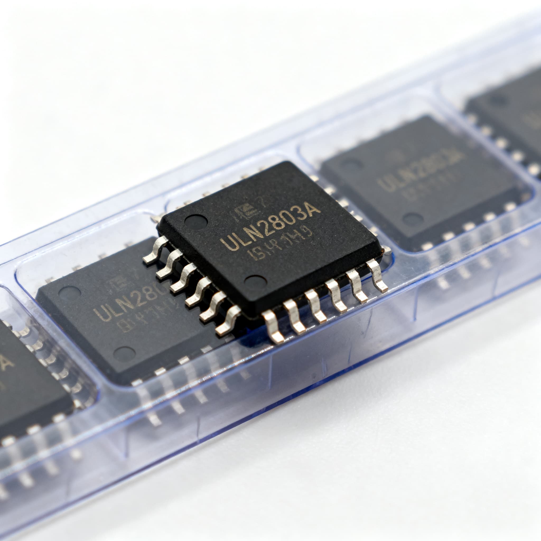
| Device marking | “ULN2803A” | Use as a first‑pass authenticity check; compare date‑code format with manufacturer pattern |
Tip: When you receive a quotation, ask the supplier to confirm that the part meets the ST datasheet Rev 4 parameters, and request a copy of the certificate of conformance. The 2.7 kΩ base resistor is integral; substitutes without it will require external resistors, increasing BOM cost and board space.
Alternatives to the ULN2803A in PDIP: Pin-Compatible Options and Neighbouring Functions
Procurement teams often look for second sources when the ULN2803A shows signs of NRND. However, the TI E2E forum is explicit: there is no direct pin‑to‑pin replacement. The forum clarifies that ULN2803AN is PDIP‑18, ULN2803ADW is SOIC‑18, and the TPL7407LAPW is TSSOP‑16. That means if your board layout expects a through‑hole PDIP, you cannot simply drop in an SOIC version without a PCB redesign. Meanwhile, the Utmel community comparison points out that the ULN2003 is a 7‑channel device, not an 8‑channel one. It can replace the ULN2803 only when one channel is unused, as in certain Prop‑1 trainer board configurations. In a standard 8‑relay driver circuit, you lose a channel—a functional gap that the RFQ must reflect.
Octopart distribution data shows that the ULN2803A remains available through multiple sources, but the part’s lifecycle status means you should evaluate alternatives now, not when the LTB is announced. Below is a comparison of the closest options and their procurement implications:
| Option | Effect on procurement / design | Notes |
|---|---|---|
| ULN2803AN (PDIP‑18) | Exact form/fit match; same part with suffix clarified | Check supplier stock; many vendors list ULN2803A and ULN2803AN interchangeably; confirm package in quote |
| ULN2803ADW (SOIC‑18) | Surface‑mount alternative; requires layout change and solder profile adjustment | Not pin‑compatible with through‑hole footprint; useful for new designs but cannot be swapped into existing PDIP boards |
| ULN2003A (PDIP‑16, 7‑ch) | Loses one channel; may require splitting loads or adding an extra driver | Only applicable if 7 channels suffice; confirm COM diode wiring for inductive loads remains adequate |
| TPL7407LAPW (TSSOP‑16, 7‑ch) | NMOS low‑side driver, different input structure; needs logic‑level adjustment | Not a Darlington; requires engineering evaluation of input current and inductive kickback protection |
The key point: your RFQ must specify the exact MPN and package required, because even the same base part number (ULN2803A) may be fulfilled with a PDIP when you expected SOIC if you don’t pin down the ordering code. For an existing 8‑channel board, the only true form‑fit option remains the ULN2803AN in PDIP. Any shift to a different package or channel count triggers a design review.
Spec-Checking a ULN2803A RFQ: Avoiding Output-Current Ratings, Package Markings, and Second-Source Pitfalls
Experienced buyers know that a single line item “ULN2803A” can hide several procurement traps. First, the 500 mA per channel rating is often interpreted as a blanket number, but the Mikroe datasheet and the official ST datasheet make clear that this is a peak current, and total power dissipation must be calculated when all eight channels are on simultaneously. If your application drives all eight outputs at 500 mA continuously, the junction temperature will exceed safe limits—the ST datasheet provides a thermal resistance of θJA that dictates a much lower continuous per‑channel current. Not verifying this in the RFQ can lead to purchasing parts that meet the “500 mA” spec but fail in-system, causing costly field returns.
Second, device marking is your first line of defense against counterfeit or remarked parts. The DiGi‑Electronics datasheet and the original ST document both show “ULN2803A” as the top marking, with a manufacturer‑specific date code format. When receiving a quotation, request a photo of the actual part marking and a lot traceability statement. This is especially critical if sourcing through non‑authorised channels, as NRND parts often attract grey market re‑marking. The SparkFun reference datasheet also confirms the marking pattern, giving you a readily available visual standard to compare against incoming samples.
Below is a checklist of actions you can take before finalising a ULN2803A RFQ:
- Confirm the manufacturer’s NRND or active status via the ST product page and check for any PCN/EOL notices that affect the PDIP‑18 variant.
- Specify the package explicitly: “ULN2803AN, PDIP‑18, through‑hole” (or the exact ordering suffix). Do not accept “ULN2803A” alone.
- Require a certificate of conformance that references DocID1536 Rev 4 or later, ensuring the 2.7 kΩ base resistor and clamp diodes are present.
- Reconcile the 500 mA rating against your actual simultaneous load; if your design drives all eight channels at max current, request derating guidance and confirm thermal pad/airflow in the system specification.
- Ask for date codes and lot numbers; cross‑check against the manufacturer’s date‑code format. Avoid lots older than 3 years unless stored in controlled conditions.
- If receiving a quote for an alternative like ULN2003A, flag it immediately: the channel count mismatch must be accepted by engineering before procurement proceeds.
| Action | When to use | Trade‑off |
|---|---|---|
| Lock in LTB quantity with an authorised distributor | When manufacturer confirms NRND and offers a Last Time Buy window | Capital tied up in inventory; shelf‑life and storage conditions become your responsibility |
| Redesign board for SOIC‑18 (ULN2803ADW) | When the product lifecycle exceeds the part’s availability window and a new PCB revision is planned | Layout and assembly change; requires requalification but secures a surface‑mount supply path |
| Adopt a 7‑channel alternative with board re‑spin | If you can consolidate to 7 channels or add an external transistor for the 8th | BOM simplification but engineering effort; verify that the driver input logic levels remain compatible |
| Use a discrete Darlington array or separate transistors | When absolute pin‑to‑pin compatibility is impossible and volumes justify a custom solution | Higher component count and PCB area; may be the only path if the ULN2803A becomes completely obsolete |
None of these actions are one‑size‑fits‑all. The right choice depends on your product lifecycle, annual usage, and tolerance for requalification. The common thread: the RFQ must capture enough detail to prevent a supplier from shipping a “compatible” part that isn’t.
ULN2803A Procurement FAQ: Package Swaps, Lifecycle Windows, and Second-Source Assurance
Q: If the ULN2803A is flagged NRND, how long do I realistically have before Last Time Buy?
A: NRND windows vary widely. FPGACenter notes it can last from one to many years, while Industrial Monitor Direct states 6–18 months is typical. Always check the manufacturer’s product status portal for YTEOL (years to end of life) and any PCN alerts, as seen on TT Electronics’ online lifecycle service.
Q: Can I drop the ULN2803ADW (SOIC) into a board laid out for the ULN2803AN (PDIP) to save space?
A: No—package and pin spacing differ completely. The ULN2803AN uses a through‑hole PDIP‑18; the ULN2803ADW is a surface‑mount SOIC‑18. A layout change is mandatory. The TI E2E forum confirms these are not pin‑compatible.
Q: Is the ULN2003A a safe second source for the ULN2803A in an 8‑relay driver circuit?
A: Not directly. The ULN2003A provides only 7 channels versus the ULN2803A’s 8. While both share Darlington arrays, using a ULN2003 leaves one output unaccounted for, requiring a design change. Utmel community guidance advises it’s a functional replacement only when 7 channels are sufficient.
Q: What spec do buyers most often overlook when quoting the ULN2803A?
A: The 500 mA output current rating is per channel but depends on duty cycle and all outputs being driven simultaneously. The ST datasheet specifies 500 mA peak, but total package dissipation must be considered. Ignoring this leads to thermal shutdown or reliability issues. The official ST datasheet provides the thermal resistance values you need for derating.
Q: How can I verify authenticity and avoid remarked ULN2803A parts during a shortage?
A: Inspect the top marking for “ULN2803A” and compare date codes. Use the official ST datasheet’s pattern as reference. Source only through authorised distributors; DiGi‑Electronics and SparkFun provide verified datasheets that help cross‑check supplier claims.
Q: Where do I find YTEOL (years to end of life) estimates for the ULN2803A?
A: Manufacturer lifecycle portals (ST, TI) publish product status including YTEOL for mature parts. The TT Electronics application note TN007 explains how to access this data online, often via a dedicated lifecycle page or a PCN subscription service.
References & Further Reading
- STMicroelectronics ULN2803A Datasheet (DocID1536 Rev 4)
- Texas Instruments ULN2803A Datasheet (SLRS049C)
- Mikroe ULN2803A Datasheet
- DiGi‑Electronics ULN2803A Datasheet
- Industrial Monitor Direct – Understanding NRND Component Status
- TT Electronics – Instant Access to Life Cycle and Obsolete Product Data (TN007)
- TDK – Product Status Information (NRND/EOL)
- FPGACenter – EOL vs NRND vs Obsolete: IC Lifecycle Status Explained
- TI E2E – ULN2803A MPN and Direct Replacement Discussion
- Components101 – ULN2803A IC Pinout, Equivalents, Features
- Utmel – ULN2803A vs ULN2003A Comparison
- Octopart – ULN2803A Price & Distributor Data
The ULN2803A may be a mature part, but your approach to sourcing it doesn’t have to be reactive. By baking lifecycle checks, pinout verification, and package‑specific MPN details into your RFQ process, you can secure supply, avoid costly redesigns, and sidestep counterfeit risk. When you’re ready to pull together a multi‑line BOM that includes this eight‑channel driver, Upload Your BOM for a consolidated quote, or Request a Quote for a single MPN—with the confidence that your spec sheet is driving the order, not guesswork.